Real-time data and sophisticated three-dimensional visualisation tools enable enhanced precision during the drilling process. Geosteering has transformed wellbore placement, resulting in improved reservoir contact, enhanced well productivity, and increased efficiency and sustainability. By dynamically adjusting to subsurface challenges, these tools facilitate the drilling of more efficient and high-performing wells.
By collaborating with a seasoned engineering and service company that is new to the region, the operator has initiated a transformative change in the geosteering process to improve well placement. The newly implemented geosteering tools offer azimuthal formation data and facilitate continuous rotation. This deployment represents a groundbreaking application of this technology for CTD, marking its inaugural use globally.
The Benefits of Directional Coiled Tubing Drilling
Coiled Tubing Drilling (CTD) has a number of important, proven benefits over traditional drilling. CTD can maintain full control of downhole and surface pressures continuously whilst drilling. CTD utilises a continuous length of steel tubing that is wound around a large reel, from which it is injected into the existing wellbore and deployed downhole. CTD has the greatest capabilities for Managed Pressure Drilling (MPD) and Underbalanced Drilling (UBD).
Facilitating Managed Pressure Drilling and Underbalanced Drilling
MPD is the precise control of the wellbore pressure profile by utilising pressure control equipment at surface to control downhole pressures in addition to the drilling fluid. UBD is a subdivision of MPD where the pressure in the wellbore is maintained below that of the formation.
The use of a continuous pipe allows CTD to facilitate uninterrupted drilling and pumping, allowing pressures to be accurately maintained and ensures underbalanced conditions throughout the entire drilling operation. In wells with low pressure, wells where there are wellbore stability risks, or in wells where the formation productivity can easily be damaged by the drilling fluid, this application is crucial. It can also enable the well to continue to produce whilst drilling and may enhance the rate of penetration (ROP) in certain scenarios.
The Benefits of a Coiled Tubed Drilling Rig
The use of a CTD decreases the time and expense associated with rig relocations as a CTD rig is generally more compact and has fewer components. This is particularly advantageous for operations in remote locations. Not needing to remove the production tubing from the well prior to drilling the new lateral is another time and cost advantage when it comes to re-entry operations.
The versatility of CTD means that it can be used for re-entry drilling to slimhole grass-roots drilling. Typical applications include: depleted wells, unconventional gas shales, underground coal gasification and coal bed methane.
Azimuthal Resistivity (AziRes) versus Traditional Geosteering
Resistivity sensors for CTD that are currently on the market can only measure bulk resistivity of the formation being drilled. However, azimuthal resistivity sensors can also predict the distance and the direction of the resistivity boundaries. Fig. 1.
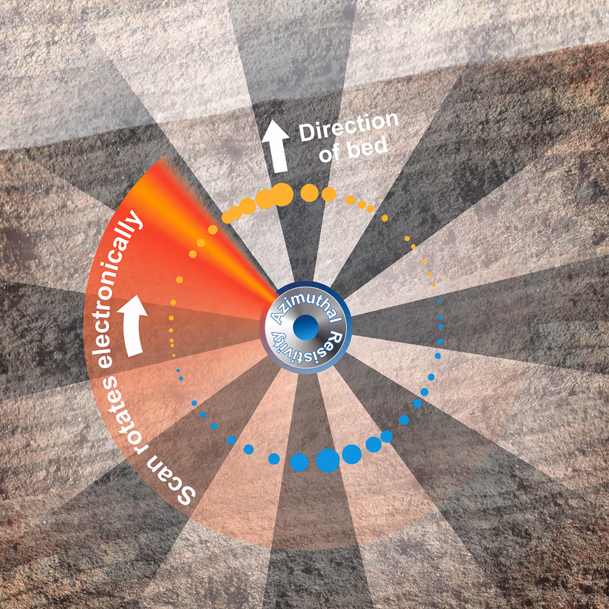
Resistivity boundaries can be bed boundaries if the formations have a different resistivity signature or oil-water/gas-water saturation contacts. Positioning the resistivity sensor as close to the bit as possible enables early detection of resistivity variations, facilitating timely directional adjustments. In conventional drilling operations the pipe is rotated from surface and therefore an azimuthal measurement can be taken by rotating a fixed resistivity sensor downhole and plotting the data points. However, in CTD, it is not possible to rotate the pipe from surface. The revolutionary technology applied by the new AziRes technology is the ability to rotate the measurement electronically so azimuthal measurements can be taken regardless of whether the tool is rotating or not.
To visualise the resistivity landscape, real-time logs and images are generated to detect formation boundaries and the presence of hydrocarbon or water saturation zones ahead of time. This saves both time and money due to the fact that the directional driller is optimally placed within the zone of interest. This technology is capable of operating in sliding mode, which makes it especially appropriate for CTD applications, due to its electrically rotated scanning feature.
Combining Directional CTD BHA Technology with AziRes Technology
CTD Bottomhole Hole Assemblies (BHA) already have the advantage of a significantly higher telemetry transmission speed, however, as part of the geosteering upgrade, the telemetry was pushed even further. A new monoconductor telemetry system was built which has allowed for transmission speeds of 50 kilobytes per second (kbps) with the potential of speeds of 250 kbps in the future. This alone opens up a broad range of potential technologies and solutions to improve geosteering and drilling efficiency.
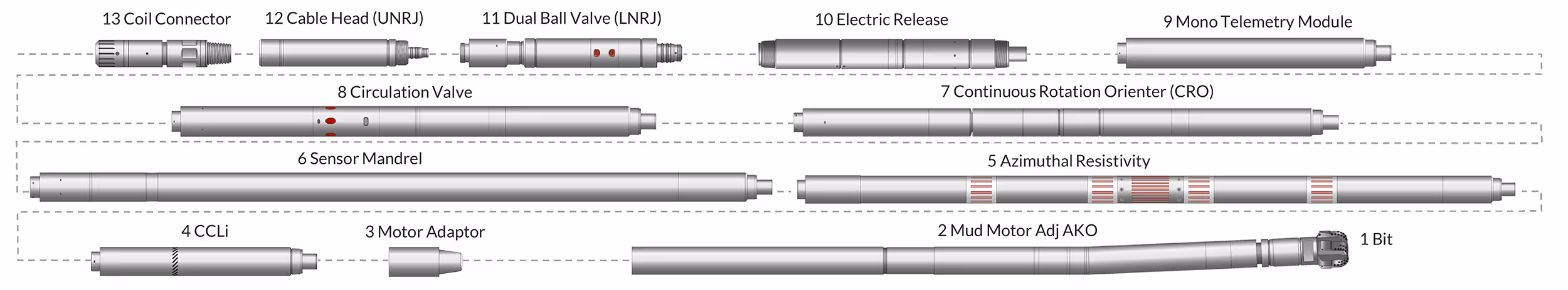
Unique technology in one CTD BHA on the market, a continuously rotating orienter (CRO) is key to the precise directional capability downhole. Built for drilling in underbalanced conditions, this particular CTD BHA has a full range of sensors giving it drill-by-wire capability and the ability to detect at-bit porosity changes. The BHA is small in diameter and targets hole sizes, between 3-5/8” and 4-3/4”. This makes it particularly suited to thru-tubing or small casing re-entries. Fig.2.
CRO of the BHA is built for precise drilling. It lets the directional driller incrementally adjust trajectory while in motion, with the build section and a perfectly straight lateral being be drilled in one run. This avoids the wavy wellbores that limit reach and weight-on-bit typically drilled with more conventional orienters.
CTD use on the North Slope of Alaska
In the early nineties, operators pioneered CTD in order to slow the decline through substantial re-entry initiatives. Donor wells for sidetracks contributed to this success and further development of the technology.
To reduce the risk of getting stuck or losing the wellbore, MPD using CTD was introduced to reduce the pressure cycles on some of the more active shale formations. MPD has now become the standard practice for CTD in Alaska.
Well No. 1: Objectives & Challenges
One of the main objectives was to geosteer a 3,000’ lateral producer within one zone. Challenges during drilling included at least one fault with a potential displacement of 15-20’, and within that continue to drill within the 20-30’ thick. Drilling in the overlying section was identified as undesirable and prolonged exposure to a lower shale layer below could lead to the need for plug backs. The drilled hole was completed with a solid cemented and perforated liner. A hybrid rig was used throughout the project as it has the capability of running continuous pipe (coiled tubing) and jointed pipe
Well No. 1: Operation Summary
The casing exit was carried out on coiled tubing using the directional CTD BHA with the incorporated casing exit equipment to set the whipstock and mill the window. The full LWD/MWD capabilities of the BHA allowed for constant monitoring of the downhole conditions and drilling parameters during the casing exit operations. One run was necessary to set the whipstock and an additional run was required to mill the window exit through the casing.
After the casing exit was complete, Azimuthal resistivity technology was incorporated for the first time in a directional CTD BHA with full MWD/LWD capabilities and used in conjunction with gamma measurements to enhance geosteering and optimise the wellbore placement within the thin reservoir. A total of 2,400’ of lateral was drilled. Unforeseen casing integrity issues led to the drilling BHA becoming temporarily detained. The electrical release mechanism was successfully activated, and the BHA was subsequently retrieved with fishing tools. In order to avoid the compromised section of casing, an additional whipstock was set higher up in the well and a new sidetrack was initiated from that point with a total length of 3,000’ of lateral drilled.
Using an orienter with the ability to continuously rotate had a positive impact on the ROP and the achievable Weight on Bit (WOB) drilling a straighter trajectory. This is the benefit of continuous rotation of the BHA while drilling horizontally and reduces the need of extended reach tools to reach the target total depth. The liner was run immediately after the drilling phase with the hybrid rig. The solid liner was set at total depth and cemented in place.
Well No. 2: Objectives & Challenges
Drilling a sidetrack with a total length of approximately 3,000 ft along a northward fault in order to achieve the production target was a key objective of Well No. 2. The main challenges associated with Well No. 2 were the enhanced lateral reach and the thin reservoir walls. By combining techniques such as azimuthal resistivity and gamma measurements, an optimally placed wellbore was delivered.
Well No. 2: Operation Summary
Coiled tubing was used to execute the casing exit, with two sidetracks drilled. The first lateral was drilled to determine the formation tops. Using insights from the first sidetrack, the second lateral was drilled and was initiated from the first lateral through an open hole sidetrack technique, employing an aluminium billet and an open hole anchor. A solid liner was then installed to total depth in a single run within the second lateral.
With the two sidetracks successfully executed, this resulted in a total drilled footage of 4,910 ft.
The lateral reach exceeded the initial requirement and ROP’s exceeding 100 ft/hr were observed way beyond in the lateral compared with existing technology. Additional insights were gained with the new geosteering technology to deliver a well optimally placed within the thin reservoir.
Geosteering and CTD tools that Benefit the Environment
With the drive towards net-zero targets very much at the forefront, the sector is looking for new and sustainable methods to reach these targets. The environmental advantages of implementing geosteering tools such as the AziRes tool and CTD can help the industry on the path towards achieving net-zero.
Geosteering
Reducing the Well Count: Less time is spent on a well through the use of geosteering tools that allow for accurate targeting of formations. Also, in some fields lesser wells are required to reach the production targets. Geosteering tools also minimise surface disturbance and noise. By maximising existing wells with geosteering solutions it also reduces the need to undertake additional drilling in the future to access untapped reserves.
Minimising Drilling Mud Usage: The reduction of the volume of drilling fluid, lessening disposal concerns and lowering costs can be achieved through reducing the overall well count.
Reducing Emissions: Lowering energy consumption and reducing greenhouse gas emissions can be achieved by reducing the amount of drilling needed. The fact that the drilling that does take place is highly efficient is also key.
The Benefits of Coiled Tubing Drilling
Land Disturbance and a Reduced Footprint: Conventional drilling takes up a sizable amount of space and in some cases this involves the levelling of land and removal of vegetation, which can have an impact on soil erosion. CTD permits operators to work on a smaller scale which allows for a smaller footprint and a significantly reduced impact on the environment.
Reducing Emissions and Noise Pollution: Emissions from machinery can be greatly reduced when CTD is introduced due to its use of smaller rigs. This also means that fuel consumption is reduced, which in-turn means lower emissions.
Using Existing Wells: Ensuring that existing wells are fully exploited means that operators are also getting the most from their investment. CTD is designed to re-enter existing wells and improve their production. CTD can access bypassed reserves as well as stimulating existing wells means that there is less need to drill new wells that impact the environment as described above.
Sidetrack Drilling: CTD can create new wells when needed, by branching off from existing wells. This means that a new well pad is not required and there is no associated land disturbance.
To view the full article, please visit: World Oil.
If you would like any further information or would like to know more about AnTech Ltd then please contact us.